Giving InMoov Four Ears, Part 1
Four microphones, two I2S buses, a real GitHub-issue bug reproduced on my own hardware, and a robot that still can't tell which way a sound came from. Part 1 is the bring-up, not the payoff.

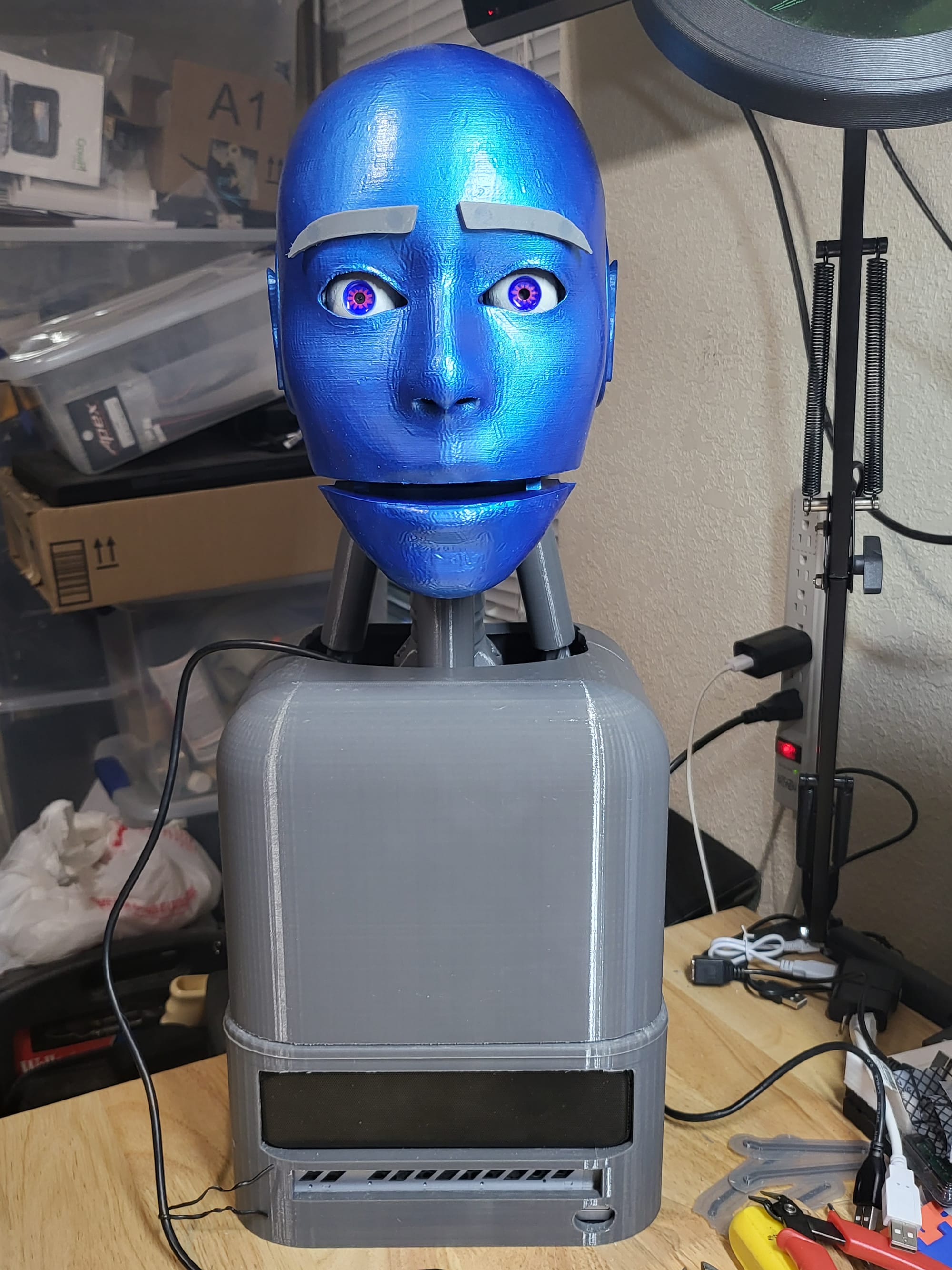
I wired four microphones to a robot's head so it could tell which direction a sound came from. This is the story of getting the hardware talking cleanly — not the story of it working yet.
InMoov, the open-source humanoid I've been slowly building, already has a form of attention: a camera and face-recognition pipeline that lets it visually track people in the room. What it doesn't have is anything acoustic. A person can turn toward a sound before they ever see who made it — a name called from another room, a dropped pan, a knock. I wanted InMoov to do the same: hear a sound, get a rough bearing on it, and use that as a hint before the camera ever gets involved.
That's a direction-of-arrival (DoA) problem, and the plan was four I2S MEMS microphones — one at each ear, one front, one rear — on an ESP32-S3, doing the timing math on-device. Here's where that plan actually stood after a day of bringing the hardware up.
What's actually in this
- ESP32-S3-N16R8 dev board — 16MB flash, 8MB octal PSRAM. Needed for two independent I2S peripherals plus enough headroom for the DSP math later.
- 4× ICS-43434 I2S MEMS microphone breakouts, bottom-port. This is what I had on hand, but worth flagging for anyone following along: TDK has since discontinued this part. Adafruit's own product page for it now says outright that the SPH0645LM4H is a drop-in replacement, and the INMP441 is what most of the open-source DoA-array projects I found actually used. Any of the three work with this wiring — just buy all four from the same batch, since sensitivity/phase matching between units matters more here than for a single mic.
- A breadboard and jumper wire, for now. This is bench prototyping, not the final in-head mounting.
- A host PC reachable over USB — in this case, the same machine that already runs the rest of InMoov's control software, which turned out to matter later in this post.
The boring-but-important decision
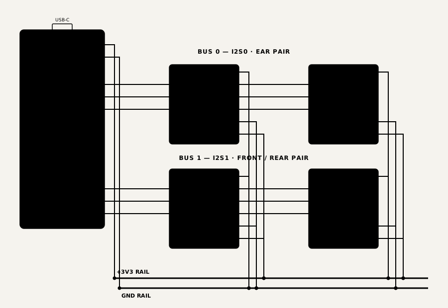
The ESP32-S3 only has two I2S peripherals, and these mic pairs are strictly two-slot devices — no way to fit all four mics on one bus. So it's two buses of two mics, and the pairing matters more than it sounds like it should. I put left+right ear on one bus and front+rear on the other, rather than splitting each stereo pair across buses. Two mics sharing a bus are sample-synchronous by hardware guarantee, so every timing comparison that actually produces an angle — left-vs-right, front-vs-rear — never needs to cross a bus boundary. I found at least one similar open-source project that split pairs the other way and had to ship a manual, runtime-tunable clock-skew slider to compensate for the two buses drifting apart. Choosing the pairing correctly meant never needing that slider at all.
Bus one, alone, first
Wiring both buses at once and hoping felt like a good way to spend a day chasing a problem that could be on either one. So: ears first, alone. Clean signal, no clipping — good. Then I tried the plan's original validation idea, clap on one side and confirm it shows up first in the correct channel, and immediately hit a wall I hadn't accounted for: at breadboard spacing, the two mics are close enough together that the real time-of-flight difference between them is a fraction of a microsecond — far below the ~21 microseconds one sample period actually resolves at 48kHz. The timing test I'd designed the whole thing around was, at this scale, unmeasurable.
The fix was almost comically low-tech: a piece of cardboard wedged between the two mics to force a real amplitude difference instead. Clap near the left mic, left channel reads louder, every time. It confirmed the wiring was right, just not by the method I'd planned on — a good early reminder that a bench test and a final-assembly test aren't always the same test.
Bus two, and a genuinely loose wire
Front and rear, same process, and this time: nothing. Exactly zero on both channels, for a solid six seconds — not quiet, actually zero, which is a different failure than "the mic is fine but nothing's happening." My first guess was a pinout mismatch. Instead of guessing further, I ran a swap test: moved the same three wires over to the known-good ear-bus pins, reflashed the unmodified ear firmware, and got a clean, healthy signal. That ruled out the mics and the wiring in one shot — the problem was specific to those three GPIO pins, not the hardware behind them. It turned out to be exactly that: a loose connection at the header. Reseated it, moved the wires back, clean signal both channels.
The bug I half-expected, and still had to earn
Running both buses at once is where I actually expected trouble. While researching this build I'd found a GitHub issue on the Arduino-ESP32 core — four of the same mics, two I2S buses, "mic pair 2 always too quiet" plus intermittent static, and notably: the symptom reversed when the initialization order of the two buses was reversed. My wiring kept each bus's clock pins fully independent specifically to design around that class of bug.
It didn't work. First combined test, the front channel started spiking to garbage values in the millions — roughly five times louder than the loudest real clap I'd recorded — while the other three channels stayed completely normal. The exact symptom, on hardware wired specifically to avoid it. Independent clock pins turned out to be necessary but not sufficient; something at the peripheral or DMA level was still contending between the two buses. I tried the one thing that issue thread suggested actually helped: swapping which bus gets initialized first. That fixed it outright — an eight-second retest afterward with all four channels correlating cleanly and zero garbage spikes.
Wiring around a known bug isn't the same as fixing it. Sometimes the fix really is just "start the other one first," and you only find that out by hitting the bug for real.
The math had its own bugs, too
With clean audio on both buses, the actual signal-processing pipeline — high-pass filter, then only bother computing anything once the sound is loud enough, then cross-correlate the pair to find the timing offset, then atan2 that into an angle — turned up two more real bugs, both interesting in the same way: they looked identical to the bug I'd just fixed.
The correlation math used double-precision floats. The ESP32-S3 has no hardware support for double precision, only single — so every one of those calculations was being emulated in software, and just slow enough to occasionally blow the roughly 10-millisecond timing budget each audio block gets before the next one has to be read. The result was the exact same kind of huge, nonsensical spike I'd seen from the dual-bus bug, for a completely different reason. Switching to single-precision floats fixed it. Separately, the threshold for "is this loud enough to bother processing" had been guessed too low — below the real, measured room-noise floor — so the expensive part of the pipeline was running on every single block instead of only the loud ones. Measuring the actual noise floor and raising the threshold above it fixed that.
Neither of these would have been obvious from reading the code. Both were obvious within a minute of looking at real numbers off the real hardware.
A small fix nobody asked for
Purely cosmetic, but worth mentioning: this board has an onboard addressable LED that defaults to a genuinely uncomfortable full-brightness white the instant it powers up. It's off now, and lights a dim blue only while the energy gate is actually open — a free, honest "I'm hearing something right now" indicator instead of a permanently blinding one.
The network question I almost overcomplicated
The original plan had the ESP32 join Wi-Fi and publish the angle over MQTT, matching how most of my other smart-home sensors report in. Partway through wiring that up, the obvious thing finally occurred to me: this board is already sitting on a USB cable connected to a fully networked machine. Giving it its own Wi-Fi credentials, its own MQTT login, its own static IP reservation — all of that would have been solving a networking problem I don't actually have. Instead, a small script on that machine reads the serial output directly and relays it into Home Assistant over the API access I already had sitting in a credentials file. Zero new credentials, zero new devices on the network, and it works. The Wi-Fi-and-MQTT version isn't wasted, though — it's exactly the right design for a future standalone mic array that isn't tethered to a host PC, and I've filed it away for that instead.
What Part 2 actually has to answer
Here's the honest state of things: the hardware is clean, the pipeline runs without corrupting itself, and a real angle number does come out the other end and land in Home Assistant. But that number isn't trustworthy yet. At the current breadboard spacing, the real timing difference between two mics on the same axis is smaller than the system can even resolve — a few microseconds, against a roughly twenty-microsecond floor. Two claps from two clearly different directions, on this bench setup, produced the identical output. That's expected, not a bug, but it means the one question this whole project exists to answer — can it actually tell where a sound came from — is still open.
Answering it needs the mics mounted at their real, head-scale spacing, which means it's waiting on the actual head shell and a final decision on which mic part to use (the one I'd planned around has since been discontinued). Part 2 is whatever happens the first time this thing gets real distance between its ears and a clap to judge.
It's the same lesson every one of these builds keeps teaching me: the interesting bugs are never the ones I expected going in.